
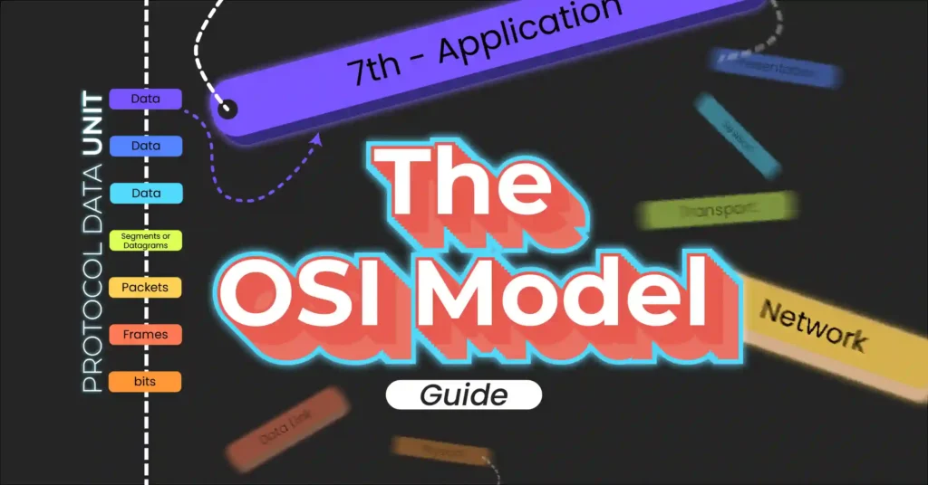
Introduction
Navigating the complexities of network communication can be challenging, but the OSI (Open Systems Interconnection) model simplifies this by breaking down network processes into seven distinct layers. In this beginner-friendly guide, we’ll explain each layer of the OSI model in straightforward terms, providing clear insights into how data flows across networks. Perfect for newcomers to networking, this post will give you a solid foundation in the OSI model and its essential functions.
Table of Contents
What is a Model?
A model is basically a simplified representation of something more complex, designed to help you understand, analyze, and work with it more effectively. Think of a construction blueprint for a building–It shows how the building is organized, how it’s divided into different rooms and spaces, and even how can be enhanced and modified in the future. It’s a simplified way to represent the structure, making it easier to comprehend the overall design.
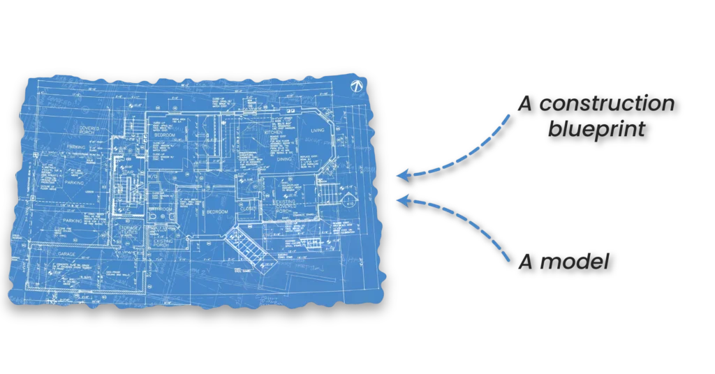
The level of detail in a model can vary, depending on its purpose. It is not necessary for a model to have all the details of the real thing. It’s just a way to simplify things and make them easier to understand.

Why do you need a Networking Model?
Networking is not simple; it involves many steps and layers, making the overall process quite complex. To better understand how networks work, we need a way to break down this complexity into smaller, more manageable parts. That is where a networking model comes in–it helps us conceptualize networks by organizing their functions into individual, simpler processes.
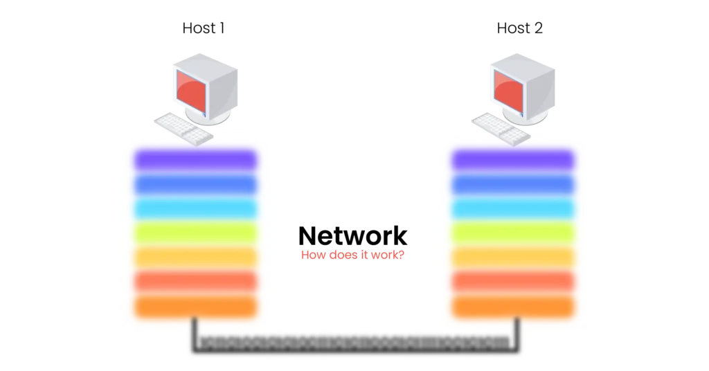
A networking model is also crucial for troubleshooting. It provides a clear mental view of a network which helps quickly identify where a problem might occur. By thinking of a network as a series of layers, each with its own specific function, you can easily determine at which layer the problem happened, and resolve issues more efficiently.
Furthermore, networking models play a key role in standardization. They allow hardware and software developers to create compatible products that can work together seamlessly, even if they come from different vendors.
In the following figure, a NETGEAR router and a Cisco router are shown working together and understanding each other’s language.

Now, let’s dive into one of the most well-known networking models: the OSI model.
The Open Systems Interconnection (OSI) Model
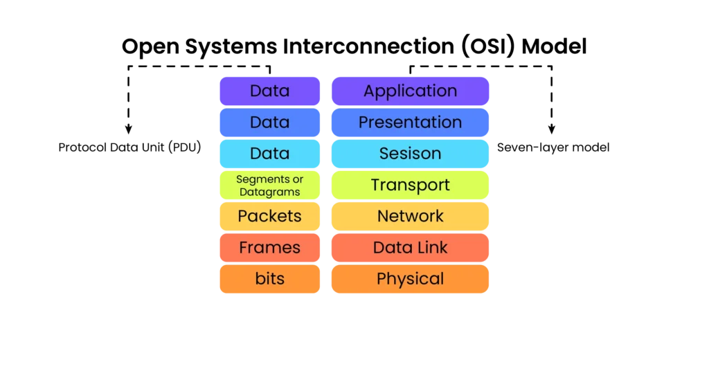
In the world of networking, the Open Systems Interconnection (OSI) model is a key reference model created in 1984 by the International Organization for Standardization (ISO). The OSI model describes how connected systems communicate with each other over a network. It shows the steps data takes as it is sent and received, ensuring it reaches its final destination intact.
In the following figure, you can see the OSI model with its 7 layers. Each has a role in a network, which helps the others in the process.
It also provides a powerful mental tool for diagnosing problems and a common language network folks use to describe specific functions of a network.
The OSI seven-layer model is often referred to as a reference model because, while it is crucial for learning and understanding networking concepts, it is not commonly implemented in full in real-world applications.
As a student of networking, understanding the OSI model is a must. Don’t worry–it will get easier each time you dive deeper into networking concepts. It will become your essential mental tool when thinking about networks.
Let’s get to know the name of each layer.
The OSI Model Layers
- Layer 7: Application
- Layer 6: Presentation
- Layer 5: Session
- Layer 4: Transport
- Layer 3: Network
- Layer 2: Data Link
- Layer 1: Physical
What does each layer represent?
Each layer in the OSI model defines a specific function in computer networking, and the protocols that operate at that layer offer solutions to these functions. These layers, together, provide everything needed to complete the whole process of sharing resources–the fundamental purpose of networks.
Before you dive into each layer, it’s important to know that each layer has something called a Protocol Data Unit (PDU). The PDU is the unit of data defined by a protocol at each layer of the OSI seven-layer model. You will learn what each layer’s PDU is called.
Let’s explore each layer individually, starting with the lowest one: the Physical layer.
The Physical Layer (Layer 1)
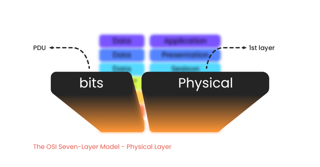
The first and lowest layer of the OSI model is the Physical layer. It focuses on aspects of physical network connections. It defines the rules for transmitting raw bits–ones and zeroes–over various physical media. This layer specifies details such as the type of cables used, the frequency required for data transmission, and the technology that determines which devices can send data at any given moment.
It is important to note that physical media doesn’t only refer to physical cables like copper or fiber-optic cables. Wireless technologies, such as Wi-Fi, are also part of the Physical layer, using radio waves to transmit data.
Network devices like hubs and repeaters operate at the Physical layer. A repeater amplifies and retransmits signals to extend their reach. A hub, which is essentially a multiport repeater, receives a signal and broadcasts copies of it to all other connected ports.
Examples of Layer 1 Technologies: Repeaters, Hubs, Cables, Radio waves
The PDU for the Physical layer is called a bit.
The Data Link Layer (Layer 2)
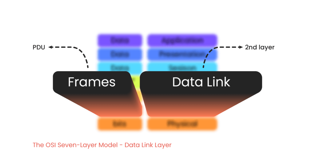
The second layer of the OSI model is the Data Link layer. It focuses on determining where data should be sent across physical ports within a network segment. At this layer, data gets addressed and directed based on Media Access Control (MAC) addresses.
The Data Link layer also provides an error-checking mechanism, ensuring that data is error-free while being transmitted over physical media.
MAC addresses, which are burned into Network Interface Cards (NICs), help the host (such as a computer) decide whether to process incoming data. When a device receives data, it examines the destination MAC address associated with the data received. If the destination MAC address matches its own, the device processes that data. If it doesn’t match, the data is simply dropped or ignored.
Note that MAC addresses are commonly referred to as physical addresses because they are tied to the hardware.
In the past, we used devices called hubs. They would take any incoming signal received on one port and sent copies out to all their other physical ports. When computers received these signals, they would check the MAC addresses to determine whether the data was intended for them.
Today, we use smart devices called switches that forward data based on MAC addresses. Unlike hubs, switches only send data for the intended host.
That’s why we need an addressing mechanism to ensure computers only process data meant for them, reducing unnecessary network traffic, and enhancing security.
Examples of Layer 2 Technologies: Bridges, switches, MAC (Media Access Control)
The PDU for the Data Link layer is called a frame.
The Network Layer (Layer 3)
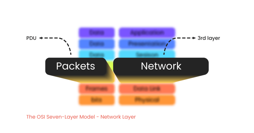
The third layer of the OSI model is the Network layer. It focuses on addressing, and managing the routing of data across different networks. This layer is responsible for delivering of data from one host on a network to another host on a different network. This layer introduces another key addressing mechanism provided by the most famous and widely used protocol at this layer, Internet Protocol (IP). There are two versions of IP currently in use: IPv4 and IPv6.
By using MAC addresses at the Data Link layer, you can identify individual devices on a network, but you cannot determine if a group of computers belongs to a specific network. MAC addresses are unique to each device, but they don’t provide information about the network to which the device is connected. That’s why we need a logical addressing system.
For network-level identification and grouping, IP addresses are used. They divide a network into logically separated networks, which require a special device called a router, to route data between different IP networks. This segmentation reduces broadcast traffic and enhances network security, by restricting broadcasts within specific segments.
Broadcasting is simply sending data from a host to all other hosts on the network without exception.
Examples of Layer 3 Technologies: Routers, IP (Internet Protocol) addresses, ICMP (Internet Control Message Protocol)
The PDU for the Network layer is called a packet.
The Transport Layer (Layer 4)
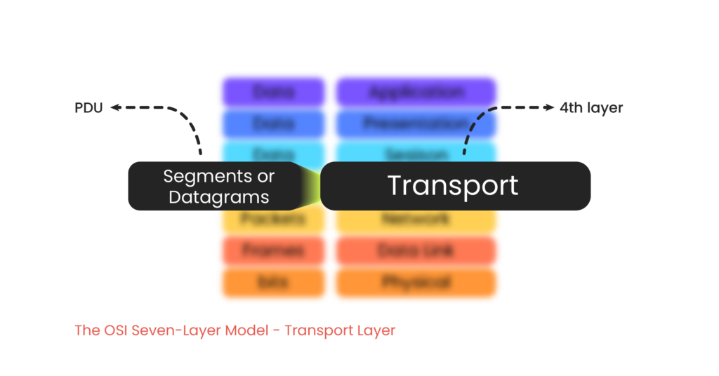
The fourth layer of the OSI model is the Transport layer. It is responsible for the delivery of data between endpoints. It uses identification numbers, known as port numbers, to determine which application on the host needs the data being received. Port numbers identify specific processes or services on networked devices.
For example, if you have multiple web browser tabs open, the Transport layer ensures that the incoming data is sent to the correct tab. Every web browser tab have a distinct port number.
These numbers are divided into source and destination port numbers. The destination port number helps the host identify which application should receive the data, while the source port number allows the host to know where to send the response data back.
Two key protocols operate at the Transport layer, Transmission Control Protocol (TCP) and User Datagram Protocol (UDP). Each has its own strengths and is suited to different requirements for data transmission.
- TCP (Transmission Control Protocol): Provides reliable, connection-oriented communication. It ensures data is transmitted accurately and in the correct order by performing segmentation and reassembly of data. TCP includes error-checking and flow control mechanisms.
- UDP (User Datagram Protocol): Offers faster, connectionless communication. While it doesn’t guarantee data delivery or order, it is efficient for applications that prioritize speed over reliability, such as streaming or online gaming.
Examples of Layer 4 Technologies: Port numbers, TCP (Transmission Control Protocol), UDP (User Datagram Protocol)
The PDU for the Transport layer is called differently depending on the protocol in use: a segment (when using TCP) and a datagram (when using UDP).
The Session Layer (Layer 5)
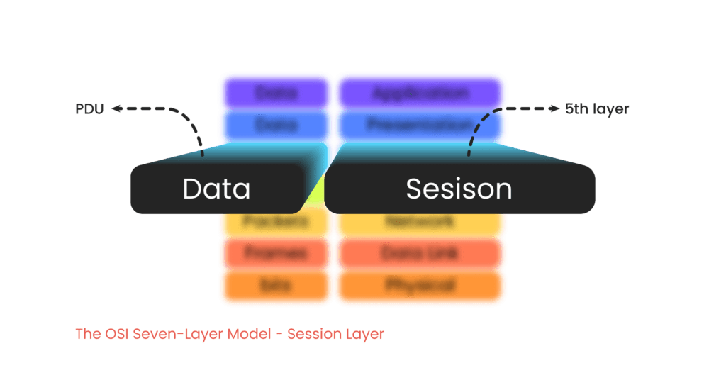
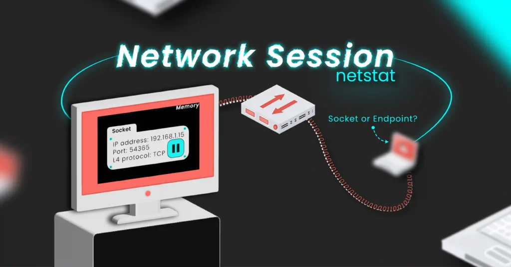
The fifth layer of the OSI model is the Session layer. It is responsible for managing sessions between systems. It handles the initiation, maintenance, and termination of sessions. In many operating systems, a session is represented using the combination of the IP address and port numbers for both sides of a TCP or UDP communication.
Examples of Layer 5 Technologies: RPC (Remote Procedure Call), NetBIOS (Network Basic Input/Output System)
The PDU for the Session layer is referred to as data.
The Presentation Layer (Layer 6)
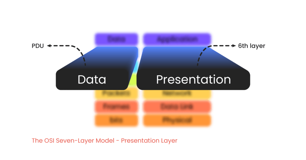
The sixth layer of the OSI model is the Presentation layer. It is responsible for translating and converting data between the formats used by the lower layers and the Application layer above. It ensures that data is presented in a format that the Application layer can understand, and vice versa.
This layer handles data encryption, compression, and conversion, making sure that the information sent from one system can be properly interpreted by the receiving system, regardless of differences in data formats.
Examples of Layer 6 Technologies: SSL / TLS (Secure Sockets Layer / Transport Layer Security), JPEG (Joint Photographic Experts Group), Encryption/Decryption protocols, Data compression algorithms
The PDU for the Presentation layer is referred to as data.
The Application Layer (Layer 7)
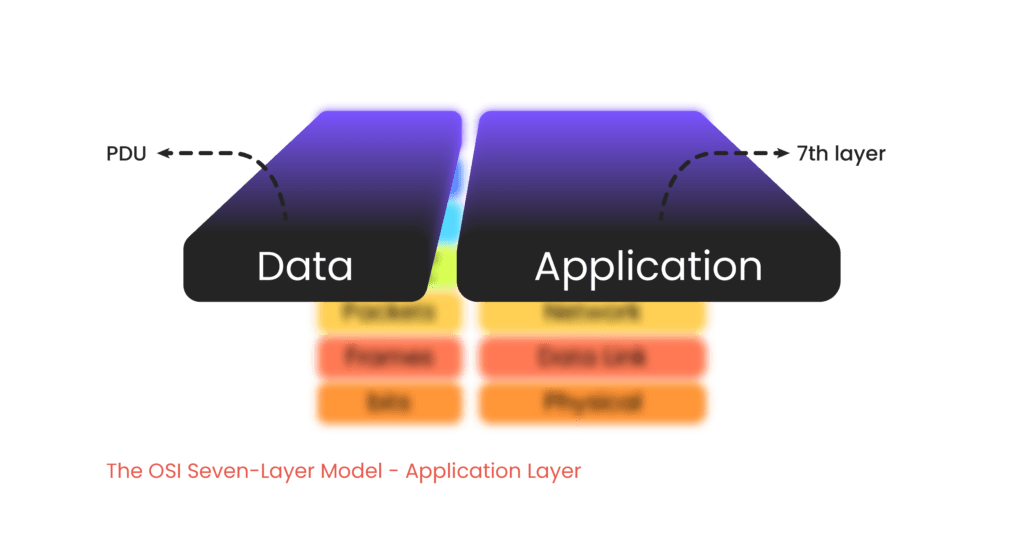
The seventh and top layer of the OSI model is the Application layer. It is responsible for providing developers with the tools they need to create network-aware applications. This layer facilitates the interaction between the application and the network.
It is important not to confuse the Application layer with the actual applications themselves. Instead, the Application layer provides an API (Application Programming Interface), which developers use to build software that can interact with the network.
Examples of Layer 7 Technologies: HTTPS (Hypertext Transfer Protocol Secure), FTP (File Transfer Protocol), SMTP (Simple Mail Transfer Protocol)
The PDU for the Application layer is referred to as data.
Conclusion
- A model is a simplified representation of the real thing to help us understand complex things.
- A networking model simplifies our understanding of how networks function, and how data is transmitted from one device to another, passing through many steps behind the scenes.
- The OSI model offers a detailed view for understanding networks, though it is mainly used as a theoretical guide rather than a practical implementation.
- The OSI seven-layer model summary:
- The Physical layer defines the rules for moving raw bits–ones and zeroes–between devices over various physical media.
- The Data Link layer ensures reliable data transfer across a physical network segment by managing MAC addressing and framing, facilitating communication between devices on the same network.
- The Network layer manages routing and logical addressing, enabling data to be efficiently directed across interconnected networks using the most well-known protocol, Internet Protocol (IP).
- The Transport layer ensures reliable data delivery between endpoints by using protocols like TCP and UDP, managing data segmentation and flow control.
- The Session layer manages and controls communication sessions between applications, handling session establishment, maintenance, and termination.
- The Presentation layer translates and formats data between the Application layer and the lower layers, handling encryption, compression, and data representation for proper communication.
- The Application layer provides the interface for network applications, offering protocols and services that enable user interaction and data exchange over the network.


2 thoughts on “OSI Model Made Easy: A Simple Guide for Networking Newbies”
Nice explanation
thank you
Thanks for your valuable feedback, Dr. Inas!